ASTRA controller, 4 Relays 16A, 8 GPIO, AC/DC power, LED (BR4G8AL)

ASTRA controller, 4 Relays 16A, 8 GPIO, AC/DC power, LED (BR4G8AL)

  • Interface: WiFi and Bluetooth;
  • Outputs: 4 Relays 16A;
  • Inputs: 8 GPIO 3.3V, direct contact to MCU, not isolated;
  • Power IN: DC 7~36V (VDC);
  • Firmware: TASMOTA, Integrated web server with web interface and MQTT protocol.

50%OFF for 1st ASTRA order

Features an impressive array of functions for individual solutions. And cost-effective, space-saving implementation, as well as comprehensive WiFi and expansion options, pay off when automating a home.
Opens up a wide range of DIY projects, smart equipment, smart home, and any control options for building functions, making it the perfect choice for fast, easy, and space-saving implementation of automation projects. Provides the right solution for the convenient control of your heating, air-conditioning, lighting, garden and irrigation, access control, garage door, presence detection, and saunas and pools.
Especially handy is the controller’s ability to connect to a smart home server as well as convenient control via smartphone, tablet, and PC through WiFi.

Wi-Fi + Bluetooth
4.2 (BR/EDR + LE)

ASTRA module builds and powerful with ESP32 microcontroller, 2.4 GHz Wi-Fi, and Bluetooth LE 4.2 (BR/EDR + LE). Two or one CPU core(s) with adjustable clock frequency, ranging from 80 MHz to 240 MHz.

ASTRA can perform as a complete standalone system or as a slave device to the main controller, reducing communication stack overhead on the main application processor. ESP32 can interface with other systems to provide Wi-Fi and Bluetooth functionality through its UART, I2C, SPI, and SDIO interfaces.

Inputs/Outputs:

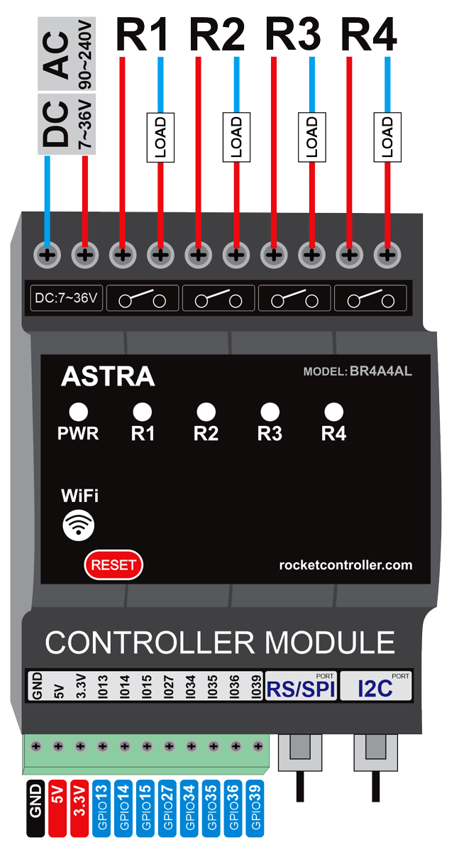
  • 4 Outputs 16A Relays (250VAC/30VDC) with LED action
  • 8 GPIO (3.3V logic level), direct contact to MCU ESP32, not isolated. To this GPIO can connect any sensors and modules for Arduino/MicroPython projects. Pins: GPIO13 (ADC/HPSI MOSI), GPIO14 (ADC/HPSI CLK), GPIO15 (ADC/HPSI CS0), GPIO27 (ADC), GPIO34 (ADC/input only), GPIO35 (ADC/input only), GPIO36 (ADC/input only), GPIO39 (ADC/input only)
  • Power Out 5V and 3.3V for powering your projects. Pins: GND, 5V, 3.3V

Power IN:

  • AC 90~240(VAC) / DC 7~36(VDC)

Internal UART and SPI socket for additional modules:

  • RS-485/Modbus RTU
  • KNX
  • Z-Wave
  • NRF24
  • USB
  • RF433/315
  • Power meter/monitoring
  • LED light driver
ASTRA GPIO8 4Relays module. I/O description

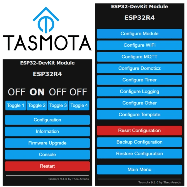
TASMOTA – Open source firmware for ASTRA

Total local control of equipment and simple interface. TAMSOTA device firmware preinstalled and configured to ASTRA controller. Easy to configure for any customs projects. Easy to update and upgrade. Multilanguage interface.
Control using MQTT, Web UI, HTTP or serial.
Automate using timers, rules or scripts.
Integration with home automation solutions.
Incredibly expandable and flexible.

Easy to migrate to ESPHome firmware or any other firmware for ESP32 microcontrollers.
ASTRA easily integrates with many home automation solutions reporting status and sensor data and allowing complete control.

  • Alexa
  • AWS IoT
  • Domoticz
  • Home Assistant
  • ESPHOME
  • Homebridge
  • HomeSeer
  • IP Symcon
  • KNX
  • NodeRed
  • nymea
  • OctoPrint
  • openHAB
  • IOBroker
  • Mozilla WebThings Adapter
  • SmartThings
Basic modules R4A4AL R4D4DL R4G4DL T4A4AL M4D4DL
4 Relays, 4 AC In, PWR AC, LED 4 Relays, 4 DC In, PWR DC, LED 4 Relays, 8 GPIO, PWR DC, LED 4 SSR, 4 AC In, PWR AC, LED 4 MOSFET, 4 DC In, PWR DC, LED
Supply voltage
Rated value (AC) 90~240V (VAC 50/110Hz) 90~240V (VAC 50/110Hz)
Rated value (DC) 7~36V (VDC) 7~36V (VDC) 7~36V (VDC)
Digital outputs 4 Relays 16A, external fusing necessary 4 Relays 16A, external fusing necessary 4 Relays 16A, external fusing necessary. 8 Input/Output (GPIO) 3.3V logic level TRIAC (SSR) 16A, external fusing necessary Transistor MOSFET 15A, external fusing necessary
Relays switching capacity of contacts VAC 240V, VDC 30V VAC 240V, VDC 30V VAC 240V, VDC 30V

 with inductive load, max. (normal use=70%max.)

10 A 10 A 10 A

 with resistive load, max. (normal use=70%max.)

16 A 16 A 16 A
Digital inputs 4 AC Isolated 4 DC Isolated, dry contact 8 Input/Output (GPIO) 3.3V logic level 4 AC Isolated 4 DC Isolated, dry contact
Analog Inputs no no no no no
Indicate
Output 4 LED (blue) 4 LED (blue) 4 LED (blue) 4 LED (blue) 4 LED (blue)
Input 4 LED (green) 4 LED (green) 4 LED (green) 4 LED (green)
WiFi status LED (blue) LED (blue) LED (blue) LED (blue) LED (blue)
Power IN LED (red) LED (red) LED (red) LED (red) LED (red)
Sound Buzzer Buzzer Buzzer Buzzer Buzzer
Mounting DIN 35mm DIN 35mm DIN 35mm DIN 35mm DIN 35mm
Basic modules R4A4AL R4D4DL R4G4DL T4A4AL M4D4DL
4 Relays, 4 AC In, PWR AC, LED 4 Relays, 4 DC In, PWR DC, LED 4 Relays, 8 GPIO, PWR DC, LED 4 SSR, 4 AC In, PWR AC, LED 4 MOSFET, 4 DC In, PWR DC, LED
Firmware TASMOTA (version link), configuration (link) (TASMOTA weblink)
Webserver integrated web server with web interface
MQTT MQTTv2
Interface Serial UART, SPI, I2C (3.3V logic level)
WiFi 802.11 b/g/n , 802.11n (2.4Ghz), up to 150Mbps
Bluetooth Bluetooth V4.2 BR/EDR and BLE specification
MCU Microcontroller Espressif ESP32-D0WDQ6, core Xtensa dual core 32-bit LX6 microprocessor, up to 600MIPS, operation voltage 3.3V
Flash memory Capacity 32Mbit (4Mbyte), NOR FLASH, SPI, operation voltage 3.3V
Basic modules R4A4AL R4D4DL R4G4DL T4A4AL M4D4DL
4 Relays, 4 AC In, PWR AC, LED 4 Relays, 4 DC In, PWR DC, LED 4 Relays, 8 GPIO, PWR DC, LED 4 SSR, 4 AC In, PWR AC, LED 4 MOSFET, 4 DC In, PWR DC, LED
Optional modules
RF433/315 optional optional optional optional optional
KNX optional optional optional optional optional
RS-485/Modubus RTE optional optional optional optional optional
CAN bus optional optional optional optional optional
Z-Wave optional optional optional optional optional
NRF24 optional optional optional optional optional
Basic modules R4A4AL R4D4DL R4G4DL T4A4AL M4D4DL
4 Relays, 4 AC In, PWR AC, LED 4 Relays, 4 DC In, PWR DC, LED 4 Relays, 8 GPIO, PWR DC, LED 4 SSR, 4 AC In, PWR AC, LED 4 MOSFET, 4 DC In, PWR DC, LED
Dimensions
Width 90mm 90mm 90mm 90mm 90mm
Height 72mm 72mm 72mm 72mm 72mm
Depth 65mm 65mm 65mm 65mm 65mm
Pakage dimensions 80mm*100mm*90mm
Weight
Netto (w/o addtiional modules) 0.24kg/0.29kg with external antenna 0.24kg/0.29kg with external antenna 0.24kg/0.29kg with external antenna
Brutto 0.29kg/0.32kg with external antenna 0.29kg/0.32kg with external antenna 0.29kg/0.32kg with external antenna
Basic modules R4A4AL R4D4DL R4G4DL T4A4AL M4D4DL
4 Relays, 4 AC In, PWR AC, LED 4 Relays, 4 DC In, PWR DC, LED 4 Relays, 8 GPIO, PWR DC, LED 4 SSR, 4 AC In, PWR AC, LED 4 MOSFET, 4 DC In, PWR DC, LED
Degree of protection IP20 IP20 IP20 IP20 IP20
Ambient conditions
Ambient temperature during operation

 min.

-20 °C; No condensation -20 °C; No condensation -20 °C; No condensation -20 °C; No condensation -20 °C; No condensation

 max.

55 °C 55 °C 55 °C 55 °C 55 °C
Ambient temperature during storage/transportation

 min.

-40 °C -40 °C -40 °C -40 °C -40 °C

 max.

70 °C 70 °C 70 °C 70 °C 70 °C
* Firmware preconfigured on manufactury. Link for download latest configuration [link]. This is details information for manual configuration or for 3-d part firmware. MCU ESP32.

Basic modules R4A4AL R4D4DL R4G4DL T4A4AL M4D4DL
4 Relays, 4 AC In, PWR AC, LED 4 Relays, 4 DC In, PWR DC, LED 4 Relays, 8 GPIO, PWR DC, LED 4 SSR, 4 AC In, PWR AC, LED 4 MOSFET, 4 DC In, PWR DC, LED
GPIO34 Input-1 Input-1 GPIO34 Input-1 Input-1
GPIO35 Input-2 Input-2 GPIO35 Input-2 Input-2
GPIO36 Input-3 Input-3 GPIO36 Input-3 Input-3
GPIO39 Input-4 Input-4 GPIO39 Input-4 Input-4
GPIO25 Relay-1 Relay-1 Relay-1 Relay-1 Relay-1
GPIO26 Relay-2 Relay-2 Relay-2 Relay-2 Relay-2
GPIO33 Relay-3 Relay-3 Relay-3 Relay-3 Relay-3
GPIO32 Relay-4 Relay-4 Relay-4 Relay-4 Relay-4
GPIO4 LED WiFi LED WiFi LED WiFi LED WiFi LED WiFi
GPIO12 Sound Buzzer Sound Buzzer Sound Buzzer Sound Buzzer Sound Buzzer
GPIO27 RF433/315 socket RF433/315 socket GPIO27 / RF433 RF433/315 socket RF433/315 socket
GPIO14 IO14
GPIO15 IO15
RXD0 Serial1 RXD Serial1 RXD Serial1 RXD Serial1 RXD Serial1 RXD
TXD0 Serial1 TXD Serial1 TXD Serial1 TXD Serial1 TXD Serial1 TXD
GPIO16 Serial2 RXD Serial2 RXD Serial2 RXD Serial2 RXD Serial2 RXD
GPIO17 Serial2 TXD Serial2 TXD Serial2 TXD Serial2 TXD Serial2 TXD
GPIO13 Serial2 CS Serial2 CS GPIO13/Serial2 CS Serial2 CS Serial2 CS
GPIO5 SPI CS0 SPI CS0 SPI CS0 SPI CS0 SPI CS0
GPIO18 SPI CLK SPI CLK SPI CLK SPI CLK SPI CLK
GPIO19 SPI MISO SPI MISO SPI MISO SPI MISO SPI MISO
GPIO23 SPI MOSI SPI MOSI SPI MOSI SPI MOSI SPI MOSI
GPIO21 I2C SDA I2C SDA I2C SDA I2C SDA I2C SDA
GPIO22 I2C SCL I2C SCL I2C SCL I2C SCL I2C SCL
GPIO2 I2C INT I2C INT I2C INT I2C INT I2C INT
GPIO0 PROG PROG PROG PROG PROG
EN RESET RESET RESET RESET RESET
Basic modules R4A4AL R4D4DL R4G4DL T4A4AL M4D4DL
4 Relays, 4 AC In, PWR AC, LED 4 Relays, 4 DC In, PWR DC, LED 4 Relays, 8 GPIO, PWR DC, LED 4 SSR, 4 AC In, PWR AC, LED 4 MOSFET, 4 DC In, PWR DC, LED
I2C
1
2 GND GND GND GND GND
3 I2C SDA I2C SDA I2C SDA I2C SDA I2C SDA
4 I2C SCL I2C SCL I2C SCL I2C SCL I2C SCL
5 I2C INT I2C INT I2C INT I2C INT I2C INT
6
RS/SPI
RS mode
1
2 GND GND GND GND GND
3 Serial2 RXD Serial2 RXD Serial2 RXD Serial2 RXD Serial2 RXD
4 Serial2 TXD Serial2 TXD Serial2 TXD Serial2 TXD Serial2 TXD
5 Serial2 CS Serial2 CS Serial2 CS Serial2 CS Serial2 CS
6
SPI mode
1 3.3V 3.3V 3.3V 3.3V 3.3V
2 GND GND GND GND GND
3 SPI MOSI SPI MOSI SPI MOSI SPI MOSI SPI MOSI
4 SPI MISO SPI MISO SPI MISO SPI MISO SPI MISO
5 SPI CLK SPI CLK SPI CLK SPI CLK SPI CLK
6 SPI CS0 SPI CS0 SPI CS0 SPI CS0 SPI CS0