This guide will help you connect and configure the relay expander to the ESP32R4 controller.
The relay expander increases the number of relays for controlled by the ESP32R4 controller. Can connect up to 12 expanders with 8 relays each. But should be aware that TASMOTA can control no more than 32 relays. Therefore, it is optimal to connect no more than 3 additional relay expanders (4 relays on the ESP32R4 controller itself + 24 (3 * 8) relays for expanders, 28 in total).
Setup steps.
Hardware:
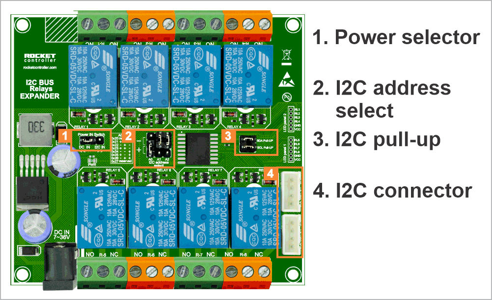
- Power supply select:
-
- DC IN voltage 7~36V. External DC power supply. Minimal power 1A.
- I2C line power IN. 5V Power In from ESP32R4 controller. Pls, to control the total power loads for the controller and I2C expanders. If ESP32R4 controller has power from AC-DC (~0.7A), it is not enough for total consumption. If ESP32R4 controller has DC power IN, needs a minimal supply of 1.7A (0.7A for ESP32R4 + 1A for relays expander), it needs to power more expander, use a power supply for ~3A.
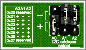
- I2C address select:For each I2C device, you need to select a UNIQUE address. Use the jumpers to set the address. Address 0x20 and 0x27 are reserved in TASMOTA and cannot be used. If you will use for other platforms, these addresses are available for use.
- I2C pull-up: For hardware operation of the I2C bus, pull-up resistors are required. Therefore, install I2C pull-up jumpers for stable operation of the device. If you need to connect more I2C devices, it is not necessary to install pull-up jumpers for them.
- I2C connectors: For connecting with a cable to the ESP32R4 controller (I2C header). 2nd port for connecting follows an I2C device.
Firmware:
- Check the version of the application that is installed on the ESP32R4 controller. Support for I2C relays expanders is included in versions starting from 11.x. If the version is below, download and install the update: TASMOTA update
- Connect relays expanders to the controller and set up the I2C address. Reset controller.
- Open TASMOTA web interface. Menu – Configuration – Configure Module. Setup GPIO for I2C:
IO GPIO21 – I2C SDA – 1
IO GPIO22 – I2C SCL – 1 - Open TASMOTA web interface. Menu – Configuration – Configure PCF8574.
- For all ports, setup Output. Save.
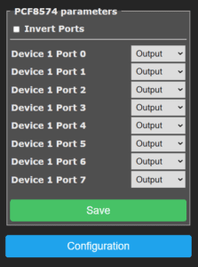
- Find new relays in main page.
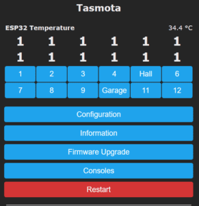
- Change the buttons name: In Console send command: WebButton<x> <NAME>For example: WebButton5 Hall *TASMOTA can change a name for buttons 1~16.
One Comment
Comments are closed.
welcome