Tasmota uses the rc-switch library to decode RF codes. The ESP32R4 controller TASMOTA firmware is already built with the RC-switch library.
The ESP32R4 controller is already configured for use RF-Receiver. If you need to change and update the setting, follow to this instruction.
Hardware.
RF-receiver header connected to GPIO27. Pin GPIO27 configured to Data pin on the RF-receiver as ‘RFrecv (106).
Software.
Open TASMOTA web interface. Menu – Configuration – Configure Module. Setup GPIO:
GPIO27 – RFrecv.
If you have an RF receiver configured, a message will be logged each time an RF code is seen. RF driver will try to decode it against all protocols supported by the rc-switch library.
When Tasmota receives an RF message, the data portion of the payload has the format as the JSON parameters to console:
“RfReceived”:{“Data”:”<hex-value>”,”Bits”:<value>,”Protocol”:<value>,”Pulse”:<value>}
This JSON payload data can be used in a rule such as:
ON RfReceived#Data=<hex-value> DO <command> ENDON
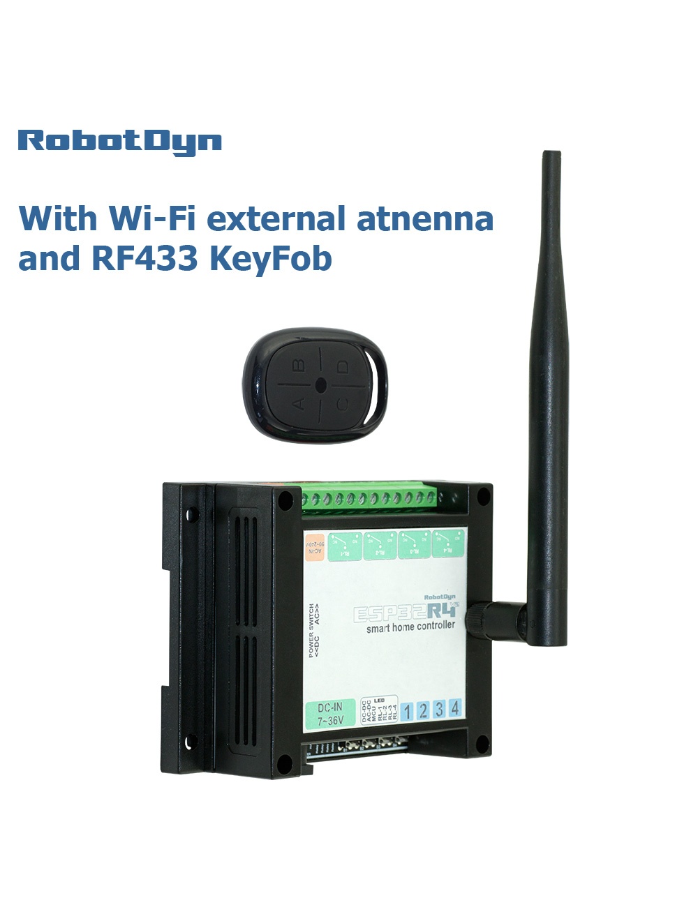
Example for 4 buttons KeyFob RF433:
Rule1 ON RfReceived#Data=0x214008 DO POWER1 2 ENDON ON RfReceived#Data=0x214004 DO POWER2 2 ENDON ON RfReceived#Data=0x214002 DO POWER3 2 ENDON ON RfReceived#Data=0x214001 DO POWER4 2 ENDON
Rule1 1
Also can use the mask of data received:
Rule1 ON RfReceived#Data$>08 DO POWER1 2 ENDON ON RfReceived#Data$>04 DO POWER2 2 ENDON ON RfReceived#Data$>02 DO POWER3 2 ENDON ON RfReceived#Data$>01 DO POWER4 2 ENDON
Rule1 1
Rule1 1 – it is the command to enable Rule1
Example for new RF-Switch:
When need to connect any RF-Wall Switch to ESP32R4 controller. 1-st check the transmission code of RF-Switch, this code you can find in console, when pressing the RF-switch:
{“Data”:”0x1E240″,”Bits”:24,”Protocol”:1,”Pulse”:351} This code “0x1E240” add to rule Rule1 ON RfReceived#Data=0x1E240 DO POWER1 2 ENDON POWER[x ] = Relay[x].
States:
- 0 / off / false = turn OFF
- 1 / on / true = turn ON
- 2 / toggle = if the power state is ON switch to OFF and vice versa
- 3 / blink = toggle power for BlinkCount times each BlinkTime duration (at the end of blink, power state is returned to pre-blink state)
- 4 / blinkoff = stop blink sequence and return power state to pre-blink state
Rules:
Rule[x] state
States:
0= disable Rule<x>1= enable Rule<x>2= toggle Rule<x>4= disable one-shot detection (perform commands as long as trigger is met)5= enable one-shot (e.g., sometimes used for slow changing sensors like temperature) detection6= toggle one-shot detection8= disable stop-on-error after exception restart9= enable stop-on-error after exception restart10= toggle stop-on-error after exception restart<value>= define Rule<x>+<value>= append to Rule<x>"= clear Rule<x>